Topological skeleton in LemnaGrid: Part IV
In a previous post of mine I explained how to use Corn Leaf Segmenter to detect leafs and to measure leaf angles. In this post, we leverage a few other skeleton graph and morphological operations to analyse the leaf insertion angle, which is defined as the angle between the stem and branching leaf blade.
How do we measure the leaf insertion angle?
Consider this image of a young corn plant.

A single leaf blade can be described with at least in one of the following shape categories:-
- straight: the leaf blade is completely erect, else it is viewed head on
- curved: the leaf is wilting, else it is too large and bends due to its weight
- From my last post we learnt that Corn Leaf Segmenter determines three points from an identified leaf:
- start (S) = leaf tip
- end (E) = insertion point
- turn (T) = turning point (if missing then T = S)
Three angles are determined of which angle beta is of our interest: using the line segment TE or SE (if T is missing) and a vertical line Y as reference that crosses E, the angle spanned between both lines is measured as the angle beta.
As can be seen from the figure above, SE is not a suitable model to estimate the insertion angle (red line): the leaf exits the insertion point with a steep slope and bends side-ways resulting in a parabolic shape.
Instead of using TS we could use other points along the leaf (S’, or S”) and construct other line segments (e.g TS’) and calculate the insertion angle more accurately. In the figure above angles measured is most accurate in this color code order: cyan > orange > red.
Rationale behind this approach
Our approach follows the conclusion from the previous section. Here we make the following assumptions:-
- the topological skeleton of the projected plant area matches the plant architecture
- the vertical reference line crossing E aligns with the stem axis to a certain degree
- a short leaf segment at insertion point is relatively straight
- the leaf segment is within a certain radius of the stem
How do we implement it
This is where you will learn how to use Graph To Object Converter. For this workshop I used a simple image of a young corn plant, in order to focus on the analysis of the leaf insertion angle.


This is the flow that we will follow: VIS image → image segmentation → plant image mask → foreground to skeleton conversion → interpret skeleton as stem and leaf → isolate stem → search leaf pixels around stem radius → measure angle between leaf and stem
Step 1: image segmentation
An image mask is created by converting the RGB image into LUV color space and then applying a suitable threshold to convert the grey scale image into a binary image. Morphological operations are applied to remove pixel artefacts accordingly.
Step 2: skeleton extraction
The foreground shape is analysed and the medial axis determined. The result is a skeleton graph consisting of skeleton joints and bones, aka nodes and edges of the graph.
Step 3: corn leaf extractor
Beginning from the lower image center, the skeleton graph is traversed from bottom to up and analysed to find connected bones that are vertically oriented. The set of of these bones is labelled as plant stem. Branching bones to the left or to the right are labelled as plant leaves.
Step 4: graph to object conversion
From the labelled skeleton graph, the plant morphological constituents are converted into lists of objects. Two image object lists are available as output: (a) leaf objects, (b) stem.
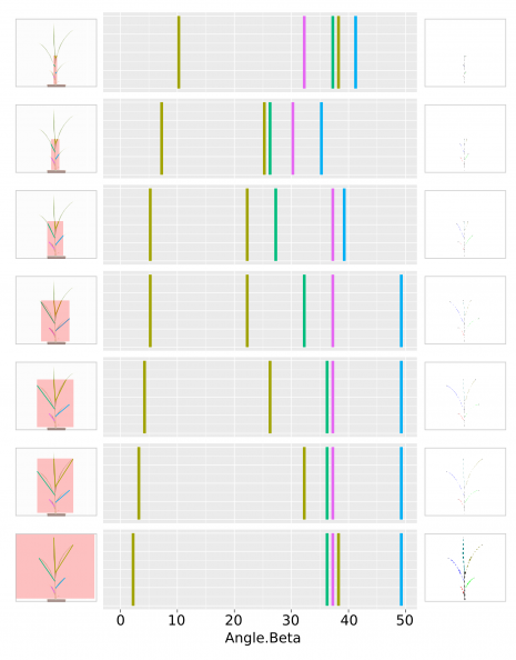
Step 5: define area of interest around the stem
The image object stem is first converted into a binary image to create an image mask. Then the mask is dilated (morphological operation) to create an area of interest (AOI).
Step 6: truncate skeleton mask
We combine the output of step 2 and step 5. The result is a truncated skeleton mask, where the stem is preserved, but the leaves are shortened.
Step 7: measure angles
Using Corn Leaf Extractor and Skeleton Graph Writer, the angle beta is determined.
Testing the approach
Testing the approach with a few different dilation steps resulting in different size of AOIs gave fairly promising results. Here is an overview of the result.
Conclusion
As can be seen, the presented approach in this post seems to be working fairly well. The measured leaf insertion angles from leaf segments with short distances after the insertion point convey that the result is more accurate than using the entire leaf.
We can off course try out more complex techniques and different approaches. However, the intent of this post was to provide readers a quick overview of how to use Graph to Object Converter to measure leaf insertion angles and the usefulness of this technique for corn trait profiling.

